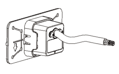
Single probe BSD blind spot monitoring and line connection auxiliary system: 77Ghz millimeter wave single probe radar
Product Introduction
This system uses millimeter wave radar sensors to monitor the environment behind and on both sides of the vehicle, monitor the blind spot of the driver's "field of view", and provide an auxiliary warning function when the driver is driving normally or changing lanes. The detection area is divided into two sections: left and right 4.4m (No alarm at ± 1.5m in the middle), a blind zone monitoring area is set at 10m towards the back. Vehicles entering the blind zone are warned, and the LED light on the same side is constantly on. When turning on the turn signal, the warning level rises to a buzzer sound, and the LED light on the same side flashes. When a vehicle changes lanes, the detection distance in the LCA lane change warning function reaches 50 meters, and the alarm distance is 40 meters. When a target vehicle approaches in the approaching area, and the collision time between the target vehicle and the vehicle is less than or equal to 5.0 seconds, the LED light on the same side remains on. If the turn signal lane change buzzer sounds at this time, the LED light on the same side flashes.Product physical image
77GHz single probe radar product diagram (universal version)

77GHz single probe radar product diagram (original model)
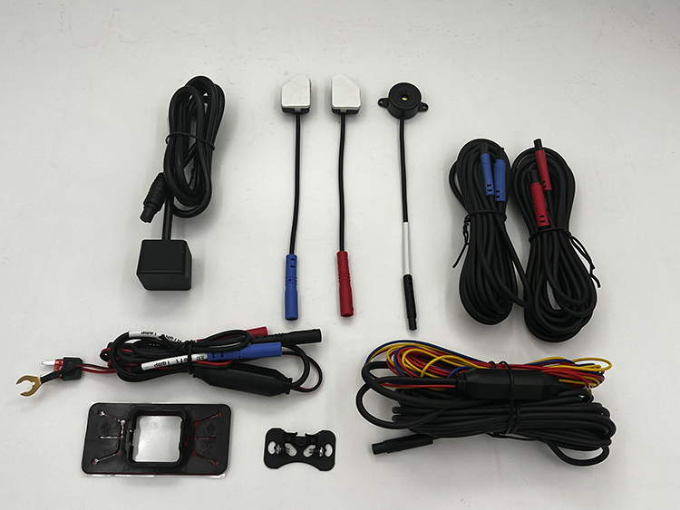
BSD blind spot monitoring and line merging auxiliary system, original left and right rearview mirrors
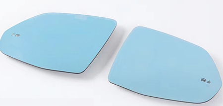
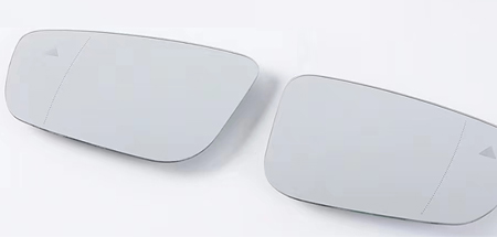
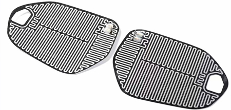
The original rearview mirror has a blue/white mirror option< Br/> Blind spot monitoring rearview mirror electric heating pad: using original factory data 1:1 mold opening, using PET+aluminum foil material. Covering the entire lens can quickly heat the lens.Blue Mirror
White mirror
Electric heating plate
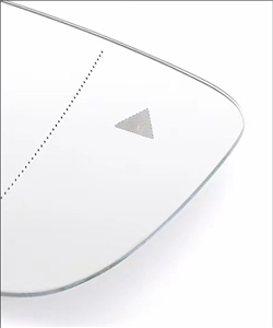
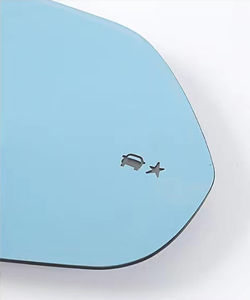
Blind spot monitoring icon
You can customize images or select the original car icon.Triangle
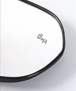
Double emblem
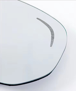
Crescent mark
Star marker
Alarm strategy
The alarm range is centered around the rear of the vehicle. The horizontal distance is X, and the vertical distance is Y. The center has a negative left lateral distance and a positive right lateral distance
Blind spot monitoring function (BSD)

System startup speed: V ≥ 10Km/h
Horizontal range of warning: 1.5m ≤ X ≤ 4.4m, -4.4m ≤ X ≤ -1.5m
Longitudinal range of warning: 0 m ≤ Y ≤ 10m
Warning strategy: Moving target alarm within the alarm area
Including active and passive overtaking, following at the same speed
Line Connection Assist (LCA)
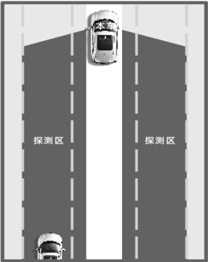
预警横向范围:1.5m≤X≤4.4m,-4.4m≤X≤-1.5m
预警纵向范围:0m<Y≤50m
预警策略:TTC≤5.0s主动超车预警功能(AOA)
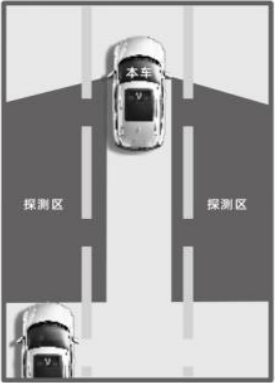
Function activation speed: V ≥ 10km/h
Horizontal range of warning: 1.5m ≤ X ≤ 4.4m, -4.4m ≤ X ≤ -1.5m
Longitudinal range of warning: 0m < Y ≤ 10mSingle probe BSD blind spot monitoring and line connection auxiliary system product parameters:
| characteristic | parameter | TECHNICAL INDEX |
| system properties | working voltage |
9-16V |
operation temperature |
-40~80℃ | |
consumption |
2.5W | |
Waterproof grade |
IP67 | |
Frequency band |
77-79GHz | |
refresh rate |
20Hz | |
communication interface |
UART | |
BAUD |
115200 | |
Shell size |
28*28*22.5mm | |
Antenna performance |
Number of transmitting and receiving channels |
3Tx*4Rx |
Pitch beam width |
±25° | |
horizontal beamwidth |
±55° | |
detection performance |
Distance resolution |
0.2m |
Velocity resolution |
0.2m/S | |
Speed measurement range |
优于0.2m | |
Range Accuracy |
优于0.2m/S | |
Speed measurement accuracy |
优于1° | |
Angle measurement accuracy |
50m | |
Detection range |
±200km/h | |
Software version |
Probe software version |
CWS-A5001_001_1.1.0_221206_RC.bin |
Hardware version |
Radar board |
HW_RF_1V0.0.0 |
Power supply backplane |
HW-CON-1V3.1.0 |
Probe Line Diagram and Parameters
Unit: mm
Installation method of radar probe
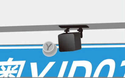
Installation method 1:
1. As shown in the right figure: The radar is installed externally
2. The installation position is next to the camera position, and this installation requires drilling and wiring; (Standard nut for punching installation)
3. The installation position is 50cm or above;External installation camera display diagram
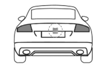
External installation display diagram
Installation method 2:
1. As shown in the right figure: The radar is installed internally
2. The installation position of the radar is external enclosure and internal measurement; (Use the matching inner mounting bracket and stick it with special adhesive)
3. The installation position is 50cm or above;Internal installation camera display diagram
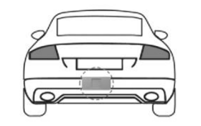
Internal installation diagram
